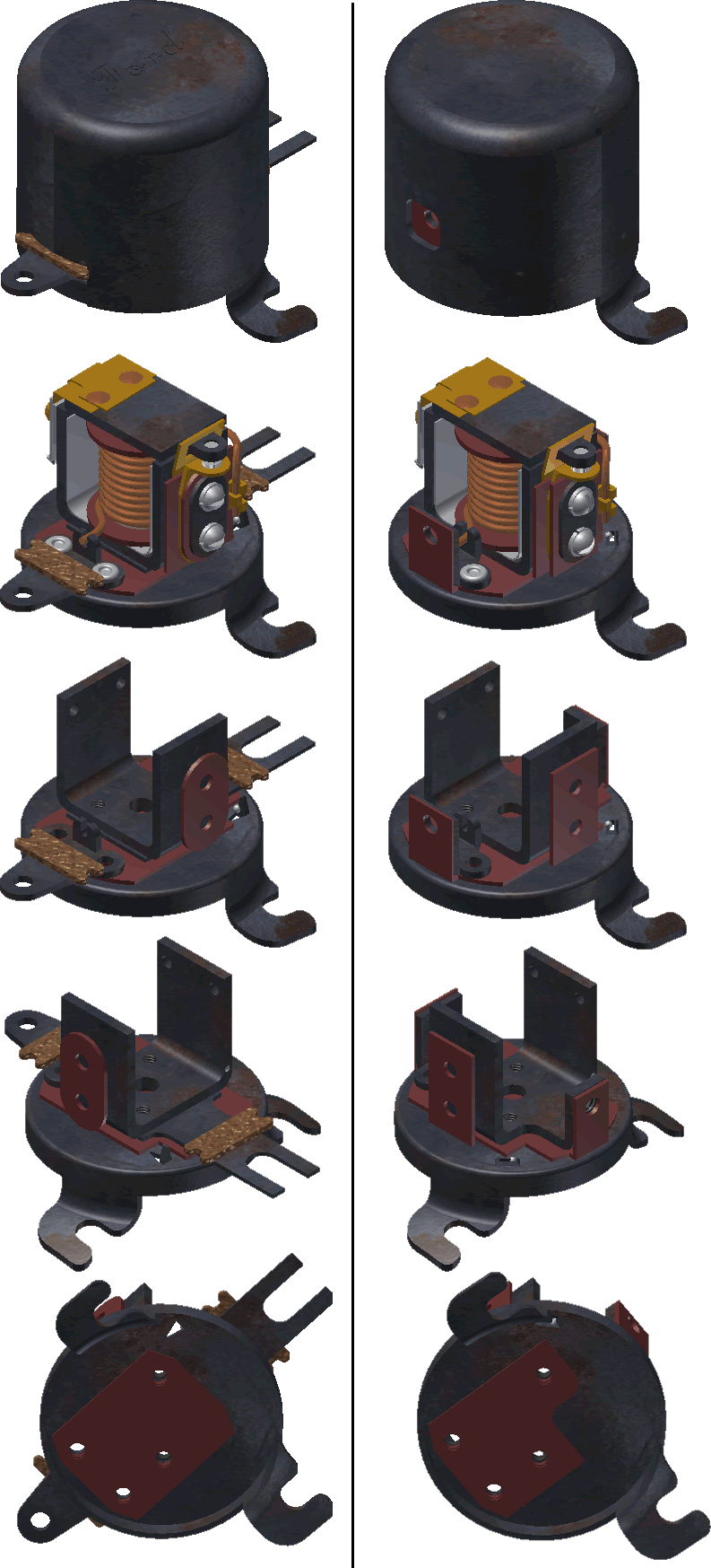
| Cutout | Exploded View | Early Vs. Later Cutout | Testing |
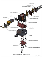
Click on the images below to download pdf drawings.
Driving tip: While driving and using an original cutout, periodically check the Ammeter to see if the system is charging. The Ammeter can be used for a quick check for the cutout. With all electrical accessories off, the Ammeter should read to the right while driving, and zero when the engine is at low idle or turned off. |
||
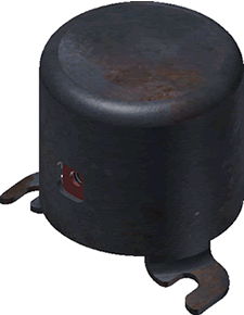
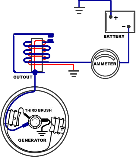
The Cutout In its simplicity a cutout is a magnetically controlled switch that provides a path for current flow from the generator to the battery. The cutout permits charging of the battery when the engine is running and prevents the battery from discharging when not.
|
 |
|
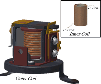
| The Coils Inner Coil-The inner coil is made up of multiple windings of a thin wire around an iron core. The fine-wire winding is just enough to get the points to close when the generator voltage rises above 6.2V or so. Its only purpose is to create a magnetic field to pull on the armature until the contact points close. By itself the magnetic field created by the inner coil is not strong enough to keep the points closed when subject to vibrating. Once the points close, the heavy-wire (Outer Coil) begins to conduct, creating a strong magnetic field that aids the inner coil in keeping the contacts firmly closed. Outer Coil-The outer coil is made with a heavy wire and few windings. With the points closed current from the generator travels thru the outer coil charging the battery and strengthening the magnetic field around the iron core which prevents the points from vibrating open. |
 |
|
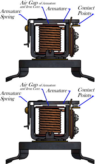
The Points Contact Points-The contact points of the cutout act as a switch and are held “Normally Open” by the armature spring. When the speed of the generator increases a magnetic field is created closing the points, thus, allowing current from the generator to flow and charge the battery. If the generator voltage drops below battery voltage, such that the battery begins to "charge" the generator ,instead of the other way around, the current in the heavy winding will be reversed, which means it's magnetic field will work AGAINST the fine winding, and cause the points to open. The point of "cut-in" (closure of points) is determined by the tension of the armature spring and the air gap between the iron core and contact arm. The contact points should close when the voltage of the generator has reached 6.1 to 6.3 volts. It is possible to change the "cut-in" by adjusting the air gap and/or bending the Armature Spring. (The "cut-in" charges the battery) The point of "cut-out" (opening of points) is determined by the tension of the Armature Spring. The air gap between the contact arm and the iron core has little or no effect on the "cut-out". The cutout should occur when the ammeter reads between 0 and 2 amps. It is possible to change the "cut-out" by bending the Armature Spring, set the "cut-out" as close to 0 as possible to prevent points from arcing and burning out. (The "cut-out"stops the charging of the battery and prevents the battery from draining) |
 |
|
Testing Cutout On Car Equipment:
|
|
|
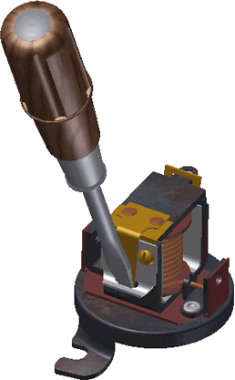
To Adjust
|
||
|
|
||
|
||
|
|
|
|
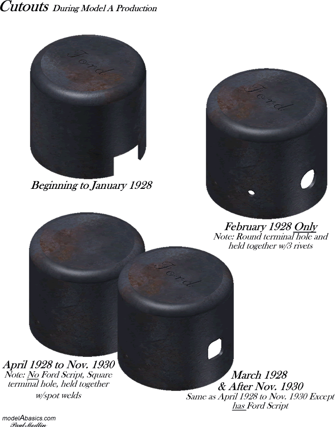
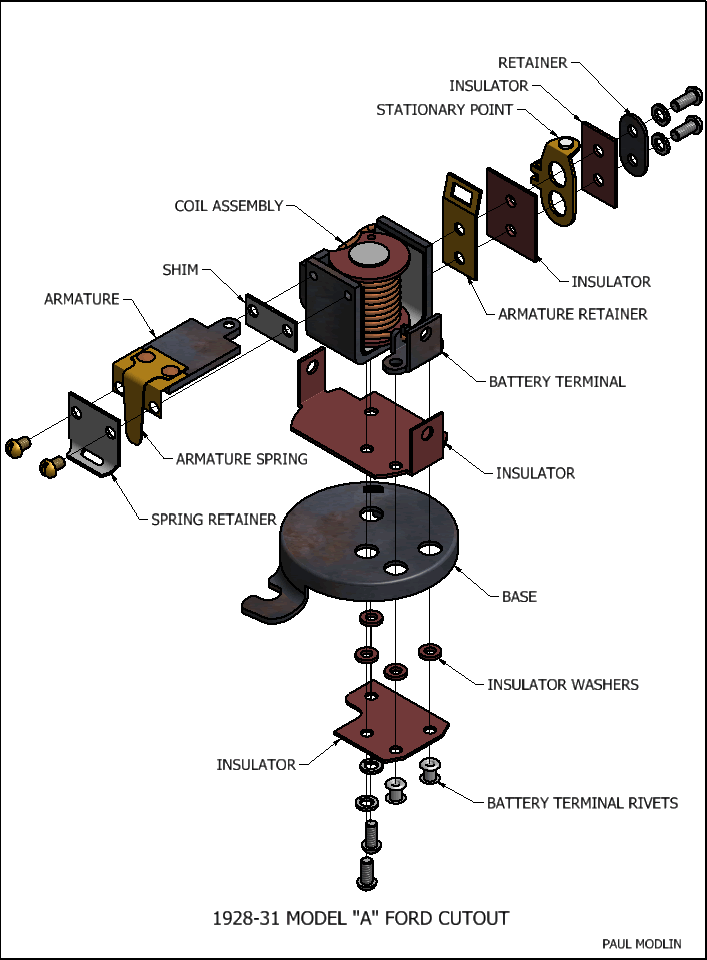
Printable pdf of above drawing
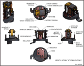
Visual Comparison of the early and later style of cutouts.
Sources:
"Automobile Repair" by S. L. Heylman and A. Edward Rhodes-Machinists' Monthly Journal Vol. XLI july 1929
MORRIS MINOR CAR CLUB OF VICTORIA INC. http://www.morrisminorvic.org.au/Voltage%20Regulator.html
Foothills Antique Tractor and Engine Club
http://web.utk.edu/~tprather/FoothillsTractorClub/TechTips/PolarizeGenerator.html
*4 Restorer's Model A Shop Manual (Motorbooks Workshop Series):
Complete & Illustrated
by Jim Schild, James J. Schild pg 152
*5 Repair Manual Generating and Starting Systems 1933-1947, Copyright 1947, Ford Motor Company, Dearborn Michigan, pg 8
The Model A Restoration Guidelines And Judging Standards, 2011 Revision, Area 2 Cutout pg 8-9
